THEORY OF STEUCTURE II LAB 1
To determine the horizontal thrust force and reaction influence lines for a point load moving across a Two-Pinned Arch.
1.2 To determine the horizontal thrust force for a uniformly distributed load on a Two-Pinned Arch.
OBJECTIVES
1.1 To determine the horizontal thrust force and reaction influence lines
for a point load moving across a Two-Pinned Arch.
1.2 To determine the horizontal thrust force for a uniformly distributed
load on a Two-Pinned Arch.
Theory:- The two hinged arch is a statically indeterminate structure of the first
degree. The horizontal thrust is the redundant reaction and is obtained y the use of
strain energy methods. Two hinged arch is made determinate by treating it as a
simply supported curved beam and horizontal thrust as a redundant reaction. The
arch spreads out under external load. Horizontal thrust is the redundant reaction is
obtained by the use of strain energy method.
The main advantage an arch has over a beam, is that it can carry a much
larger load. Historically arches were important because they could be
constructed using small, easily carried blocks of brick or stone rather than
using a massive, monolithic stone beam or lentil. Romans used the
semicircular arch in bridges, aqueducts, and in large-scale architecture. In
most cases they did not use mortar, relying simply on the precision of their
stone finish. When an arch is loaded by gravity forces, the pressure acts
downward on the arch and has the effect of compressing it together instead
of pulling it apart. A free body diagram of the arch supports shows the arch
requires both horizontal and vertical reaction forces (Figure 1).

One of the disadvantages of the arch resisting loads in compression is the
possibility that the arch may buckle. Any practical arch design would
include analysis involving stress, deflection and buckling. To perform such
analysis, reaction forces, shear and moment diagrams are needed for a given
load case. Since the arch is indeterminate, having more unknown reactions
forces than equilibrium equations, methods such as the flexibility method
are required to determine the reaction forces.
EQUIPMENT LIST
1. Structures test frame
2. Digital force display
3. Load cell and power supply
4. Aluminum arch, hangers and weights
5. Scale
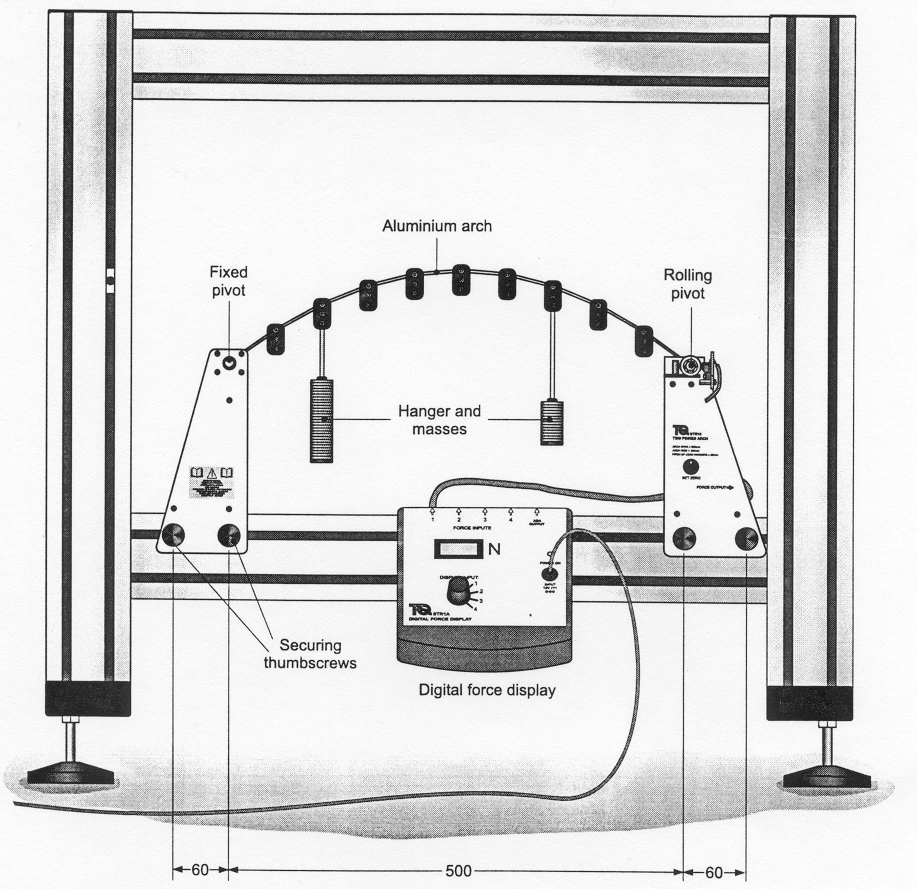
Procedure
Carefully zero the force meter using the dial on the right-hand side
support. Gently apply a small load with a finger to the crown of the arch
and release. Zero the meter again if necessary.
NEVER apply excessive loads to any part of the equipment or strike the
Load Cell.
PART A
The first experiment is to measure the horizontal thrust force HB for a single
load that is placed at increasing distances from the left support. A
theoretical equation for the horizontal thrust force for a given load W at
location x, is given below:
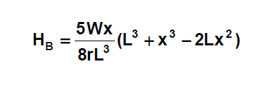
Where:
HB = The horizontal thrust reaction at B (N)
W = Load (N)
L = Span of the arch (m)
x = Load location, distance from the left-hand side support (m)
r = Rise of the arch (m)
4.1A Measure the necessary dimensions of the two-pinned arch and record
the data.
4.2A Adjust the “set zero” control on the right support so that the digital
force reads zero.
4.3A Apply a 100 gm load to the left most hanger and record the thrust
force. Moving the 100 gm load to the remaining hangers and record
the thrust force for each location. Repeat the process for a 500 gm
load. The horizontal thrust shown on the digital force display has units
of Newtons
PART B
The second part of the experiment involves determining the horizontal thrust
force for a uniform or distributed load w. The equation for the thrust force is
given in Equation 9.2.
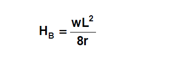
Where:
HB = The horizontal thrust reaction at B (N)
w = Uniform distributed load (N/m)
L = Span of the arch (m)
r = Rise of the arch (m)
4.1B Adjust the “set zero” control on the right support so that the digital
force reads zero.
4.2B Apply 50 gm on each of the nine hangers (total of 450gm) and record
the thrust force. Repeat the procedure with 60 gm on each hanger
(540) gm total).
OBSERVATION & CALCULATION


You may also like
eartquake protection:building technology

numerical method note
